Water Level Indicator using PCB
Project Details:
➢ Introduction:
This project is about the indication of water in the tank of its level. It is useful from overflow of water by tank.
➢ Components:
The components that are installed is project are:
1. PCB.
2. 3 LED’s.
3. Buzzer.
4. 4 Resistor of 1KΩ.
5. 3 Resistor of 470RΩ.
6. Battery.
7. 4 PNP Transistor (A1015).
8. Switch.
➢ Specifications:
Every components listed above are to be connected on the PCB. All components are of specified configuration.
Three LED’s of different colors require 3V DC light emitting diode. It require current of 20mA.
The installed buzzer require 5V current for proper functioning.
Three resistors of 470R are used to limit the maximum base current.
Four resistors of 1KΩ are used for sensing whether the wire is in contact with the water or not.
Four PNP Transistors of model A1015 are used because it provide sensor current to the resistor which is connected with the wire, which is in contact with the water.
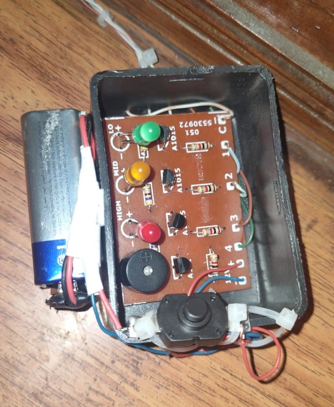
9V battery is used for providing voltage to the device to work properly.
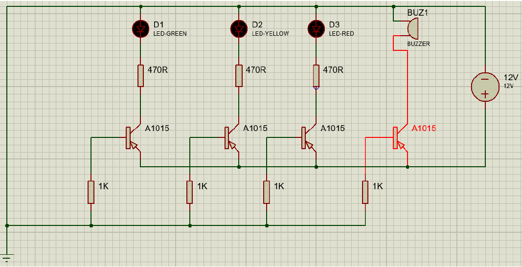
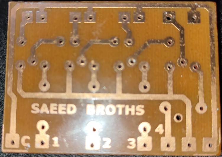
➢ Schematic Diagram:
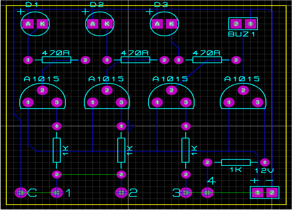
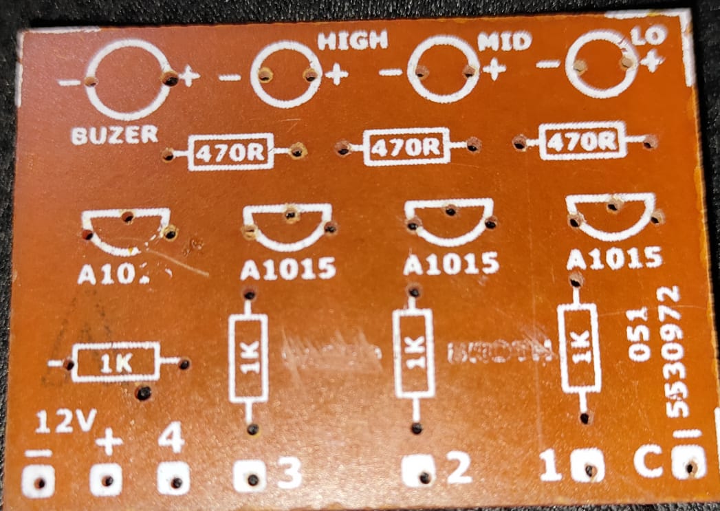
➢ PCB Schematic:
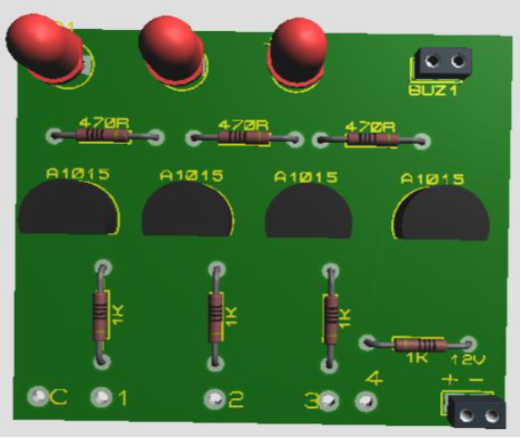
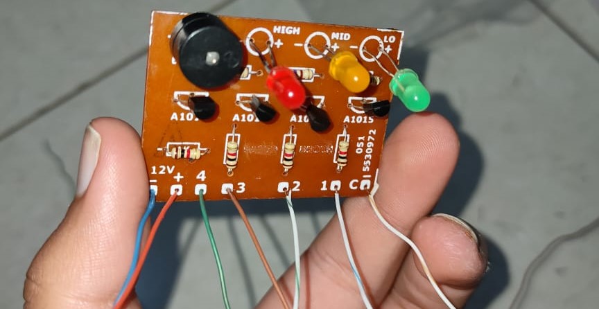
➢ Construction:
The positive terminal of battery is connected with the emitter of every single transistor. Whereas the negative terminal of the battery is connected with the negative terminal of the buzzer and also with the negative terminal of the LED’s. Now the same wire will be poured in the water. All LED’s are separately connected with the 470R resistor is series. The second terminal of every resistor is connected with the collector of every transistor. Similarly, the positive terminal of the buzzer is connected with the collector of transistor. The base of every transistor is connected with the resistor of 1KΩ resistance. At last the second terminal of the resistor is connected with the wire.
➢ Working:
The water in the tank when crosses the different level of the tank where wires ate attached the LEDs would glow to determine the different level of water.
The buzzer will make noise when water reaches till the overflowing point.
Play the Video to see how our Project Works.