Darkness Sensor Circuit
Project Details:
➢ Abstract:
Automatic Night Lamp with is a simple yet powerful concept, which uses transistor as a switch. By using this system manual works are 100% removed. It automatically switches ON lights when the sunlight goes below the visible region of our eyes.
This is done by a sensor called Light Dependent Resistor (LDR) which senses the light like our eyes. It automatically switches OFF lights whenever the sunlight comes, visible to our eyes and activates the/ morning alarm. By using this system energy consumption is also reduced because nowadays the manually operated streetlights are not switched off even the sunlight comes and switched on earlier before sunset. In this project, no need of manual operation like ON time and OFF time setting. LDR and transistor are the main components of the project. The resistance of light dependent resistor (LDR) varies according to the light falling on it.
This LDR is connected as biasing resistor of the transistor. According to the light falls on the LDR, the transistor is operated in saturation and cut off region. This transistor switches the relay to switch on / off the light. This project uses A battery.
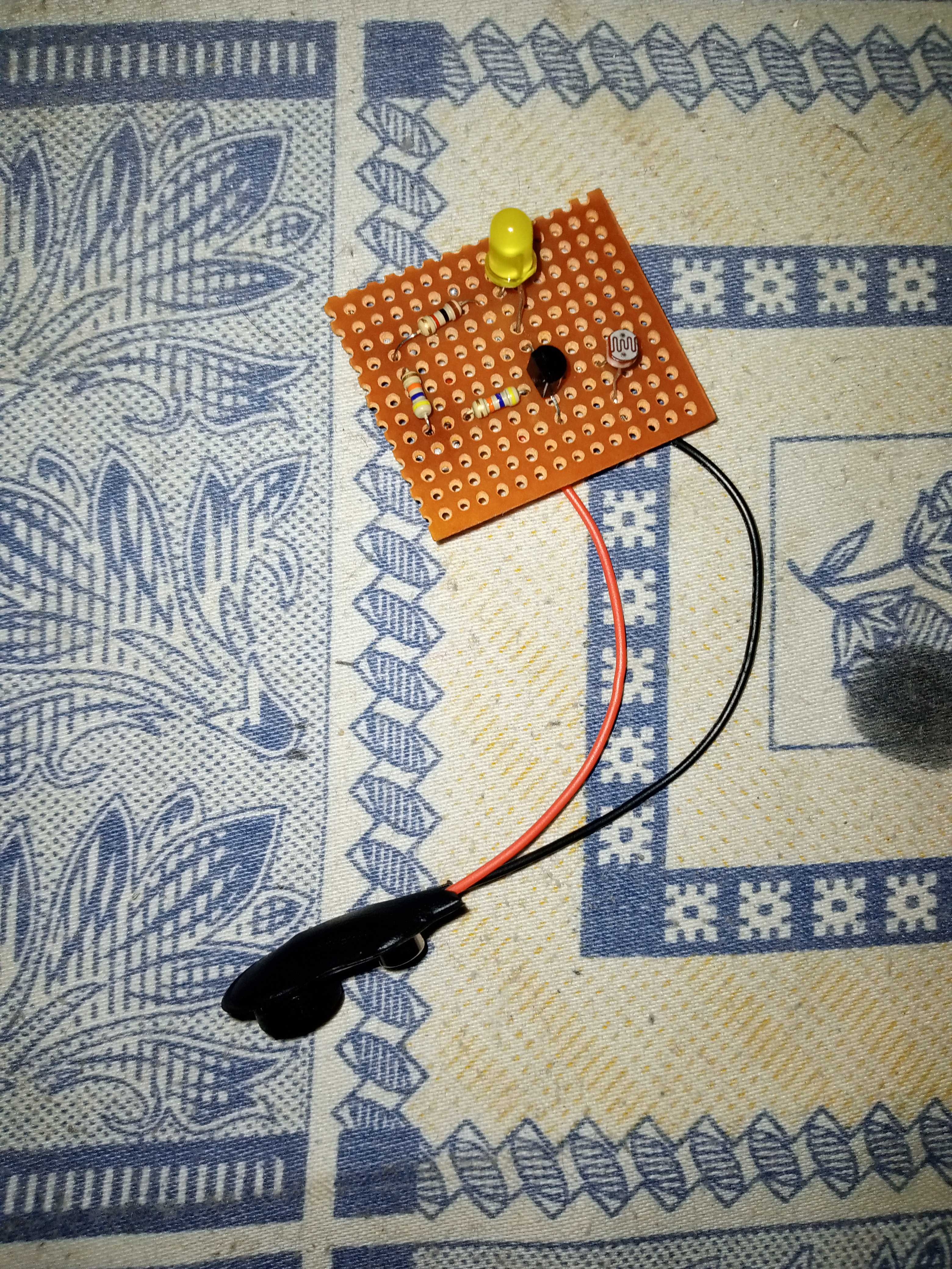
➢ Components Required:
| S.No | Components | Range/Type | Quantity |
|---|---|---|---|
| 1 | Transistor | BC 547 | 1 |
| 2 | LDR | - | 1 |
| 3 | Resistor | Less than 1K, 100K | 1,1 |
| 4 | Battery | 9V | 1 |
| 5 | LED | white or green | 1 |
| 6 | Veroboard | - | 1 |
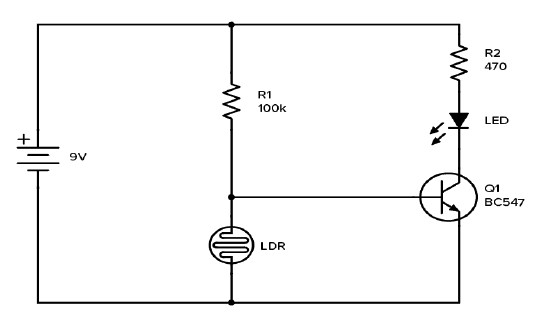
➢ Components Diagram:
➢ Circuit Explanation:
This circuit automatically turns on a night it gets dark. The lamp remains
‘on’ until the light sensor senses daylight in the morning. A bright LED is
used in the night switch. The circuit is powered by a battery. The circuit
utilizes light de pendent resistors (LDRs) for sensing darkness and light.
The resistance of LDR is very high in darkness, which reduces to
minimum when LDR is fully illuminated in daytime in total darkness, the
white LED to glow glow.
The LDR and the 100 kΩ resistor make up a divider. When there is a lot of
light, the LDR will have low resistance, which means the voltage divider
gives a low output voltage. So, the transistor is off and cuts off the
current to the LED. Which means no light.
When it is dark, the LDR will have high resistance. That means the
voltage divider gives a high output voltage which turns on the transistor.
That means the LED is also on and will light up.
When it is light and the LDR will have low resistance, the output from
the voltage divider is around 0.5V, which is not enough t o turn on the
transistor. When it is dark and the LDR will have high resistance, the
output from an unconnected voltage divider would be around 4.5V.
But since the output of the voltage divider is connected on the base of
the transistor, the voltag e will be limited by the forward voltage of the
base emitter connection (around 0.7V).
➢ Conclusion:
This circuit is highly helpful. It is an energy saving circuit that help in
saving energy as it turns on light when it is dark and turn off when it is
day.
Play the following Videos to see how our Project Works.