Wireless AC Detector
Project Details:
A current sensor circuit is a circuit that can sense current going through it. If the current reaches a certain threshold, then an indicator, such as an LED, will turn on.
Working:
The concept of working behind this project is that a live wire has alternating current flowing through it. These also radiate from the wires and hence can be felt by a nearby sensing circuit which is properly tuned to do so. The project has a coil which does this task of receiving these radiated waves. The received waves are then converted into a human recognizable form with the help of a processing circuitry. Thus, the circuit switch on LED to let the user with the device inspecting the live wire know that there is a current flowing through the live wire. An antenna is an important part of any circuitry which is intended to receive incoming wireless signals. The radiated AC line signals are received by this antenna. These signals are then amplified and fed to the LED blink.
➢ What is BC547 Transistor Working and Its Applications:
The semiconductor device like a transistor is one kind of switch which controls electrically. It consists of three terminals like an i/p, o/p & a control line. These are named as the emitter (E), collector(C) and base (B). A transistor works like a switch as well as an amplifier to convert the waves from audio to electronic. Transistors are smaller in size, long life and can operate with low voltage supplies. The first transistor was designed with Ge (germanium). In modern electronics, it is the basic building block and used in various electrical and electronic systems.
➢ What is a BC547 Transistor?
The BC547 transistor is an NPN transistor. A transistor is nothing but the transfer of resistance which is used for amplifying the current. A small current of the base terminal of this transistor will control the large current of emitter and base terminals. The main function of this transistor is to amplify as well as switching purposes. The maximum gain current of this transistor is 800A.
Similar transistors are like BC548 & BC549. This transistor works in a fixed DC voltage in the preferred region of its characteristics which is called the biasing. Further, the series of this transistor can be divided into three groups based on the current gain like BC547A, BC547B & BC547C.
➢ BC547 Transistor Pin Configuration:
The BC547 transistor includes the following.
• Pin 1 (Collector): This pin is denoted with symbol ‘C’ and the flow of current will be through the collector terminal.
• Pin 2 (Base): This pin controls the transistor biasing.
• Pin 3 (Emitter): The current supplies out through emitter terminal.
A Transistor works as an amplifier while functions in the active region to amplify voltage, current, and power at various configurations. The amplifier circuit uses three configurations which include the following.
• Common emitter (CE) amplifier
• Common collector (CC) amplifier
• Common base (CB) amplifier
From the above three configurations, CE is the most widely used configuration.
➢ Working States of Transistor:
The working states of BC547 transistor includes the following.
• Forward Bias.
• Reverse Bias.
In a forward bias mode, the two terminals like emitter & collector are connected to allow the flow of current through it. Whereas in a reverse bias mode, it does not allow the flow of current through it because it works as an open switch.
➢ Features:
The features of the BC547 transistor include the following.
• The gain of DC current (hFE) = 800 A
• Continuous 𝐼𝐶 (collector current) = 100mA
• VBE (emitter-base voltage) = 6V
• 𝐼𝐵 (Base current) = 5mA
• The polarity of the transistor is NPN
• The transition frequency is 300MHz
• It is obtainable in semiconductor package like-92
• Power dissipation is 625mW
Components:
1. BC547 transistors x3
2. LED x1
3. 220 Ohm resistor x1
4. Spring (ballpoint spring or copper wire) x1
5. 9V Battery x1
6. 9V Battery clip x1
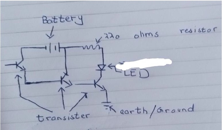
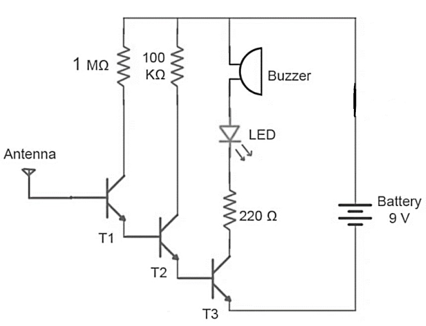
Circuit diagram:
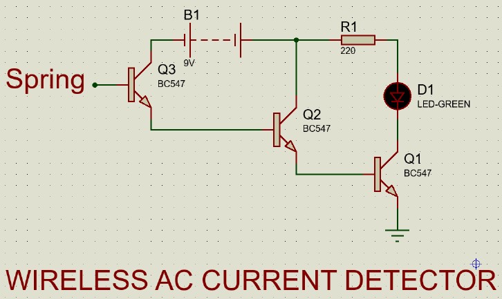
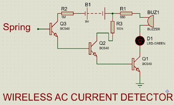
Proteus Diagram:
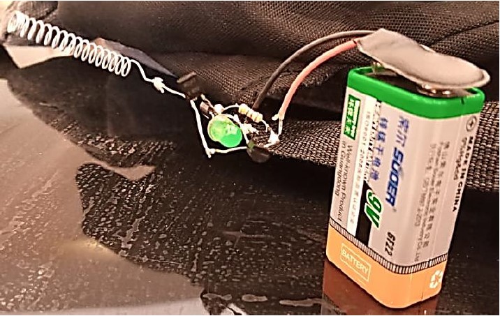
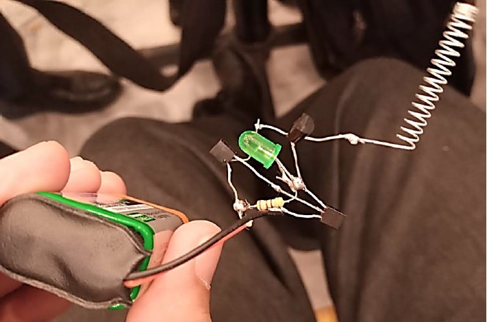
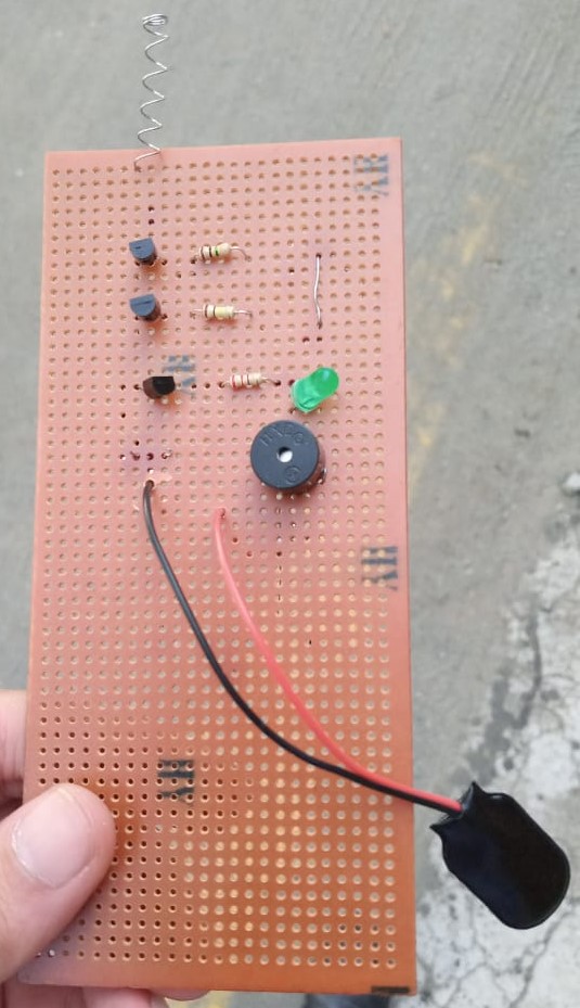
Our Project (Version One):
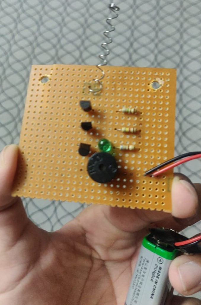
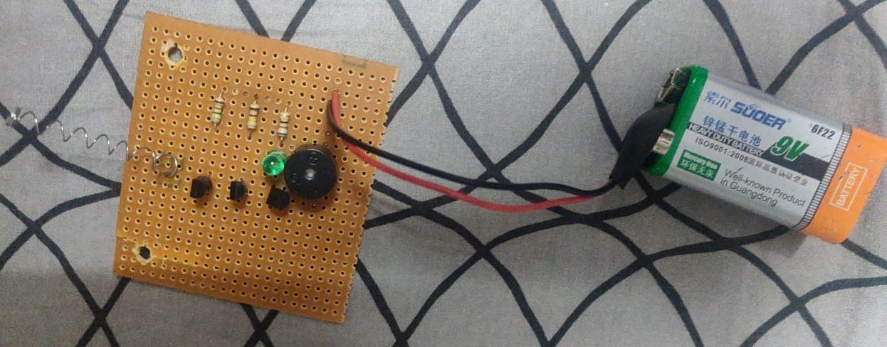
Our Project with a Different Designed Circuit on Vero Board:
➢ Components:
1. BC547 Transistors x3
2. BC548 Transistors x3
3. Resistor 1.0 MΩ x1
4. Resistor 100kΩ x1
5. Resistor 220Ω x1
6. Resistor 680Ω x1
7. LED, Green x1
8. Buzzer x1
9. 9V Battery x1
10. Spring (ballpoint spring or copper wire) x1
➢ How does this work?
A magnetic field is produced around a current carrying conductor and if current through the conductor is alternating current (AC), the magnetic field produced varies periodically. A non-contact AC voltage detector detects the changing magnetic field around AC energized objects.
This non-contact AC voltage detector uses NPN type transistors in order to detect voltage. A transistor has three terminals - collector, emitter and base. Collector to emitter current is controlled by the base current. When there is no base current, no collector to emitter current flows. Thus, a transistor acts as a switch. It can be 'ON', it can be OFF or in-between.
The ratio of collector current to base current is known as the gain of a transistor. Normally, gain of 2N3904 is about 200, i.e. collector to emitter current can be as high as 200 times the base current. If we connect the output of one transistor to the base of another transistor, the total gain would be multiplication of the two i.e. 200x200 = 40000. Thus, if we connect three transistors in such configuration, the total gain would be 200x200x200 = 8,000,000. Therefore, an extremely small signal can be used to switch ON a normal circuit by using such configuration of transistors.
In our circuit, an antenna (Spring) or copper wire is connected to the base of first transistor. When we place this antenna near an object that is AC energized, a small current gets induced into the antenna due to electromagnetic induction. This current triggers the first transistor and output of the first transistor triggers the second and third. The third transistor switches ON the LED and buzzer circuit, indicating that AC voltage is present.
➢ Circuit diagram:
➢ Proteus Diagram (Slightly Different):
➢ Our Project (Version Two):
According to Proteus circuit diagram
Back to Projects